
Such a representation is very helpful for analysis purposes. The equivalent circuit of an op-amp is the circuit where the op-amp parameters are represented in terms of physical components. Op-amp will then determine which of the two signals has a greater magnitude. There will be one voltage signal which will be used as a reference and another signal which is to be compared. The metallic pick-up sensor is wired to the input at pin 2 and should be placed extremely near to the IC. Through a couple of 4M7 feedback resistors hooked up between the negative input at pin 2 and the amp's output at pin 6, the amplifier's gain is adjusted to almost maximum. In this case, it compares two analogs signals. The main operational element in this circuit is a 741 op-amp IC. Here is a circuit diagram of Op-amp IC being used as a comparatorĬomparator as the name suggests compares two things.

Op-amp is a collection of transistors and resistances as you can see from the picture. The nonlinear resistor is implemented by two linear resistors and two diodes, while on the right side of the circuit is an operational amplifier negative. An operational amplifier has two input pins and one output pin.

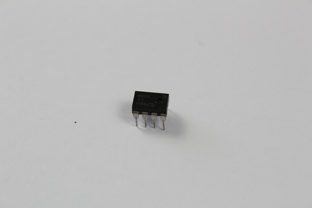
The different terminals are marked in different colors. Some integrated circuit packages will have a small round indentation or a dot next to pin 1 to. An operational amplifier is an integrated circuit that can amplify weak electric signals. The internal circuit diagram of an op-amp IC is given below:Īs you can see above, the non-inverting terminal and offset null are located at the left.


 0 kommentar(er)
